Amikon Limited factory
  • Which automation projects is the Allen-Bradley 1769-L36ERM suitable for? Technical features, industry applications, and selection guide
    Which automation projects is the Allen-Bradley 1769-L36ERM suitable for? Technical features, industry applications, and selection guide 2026-09-01
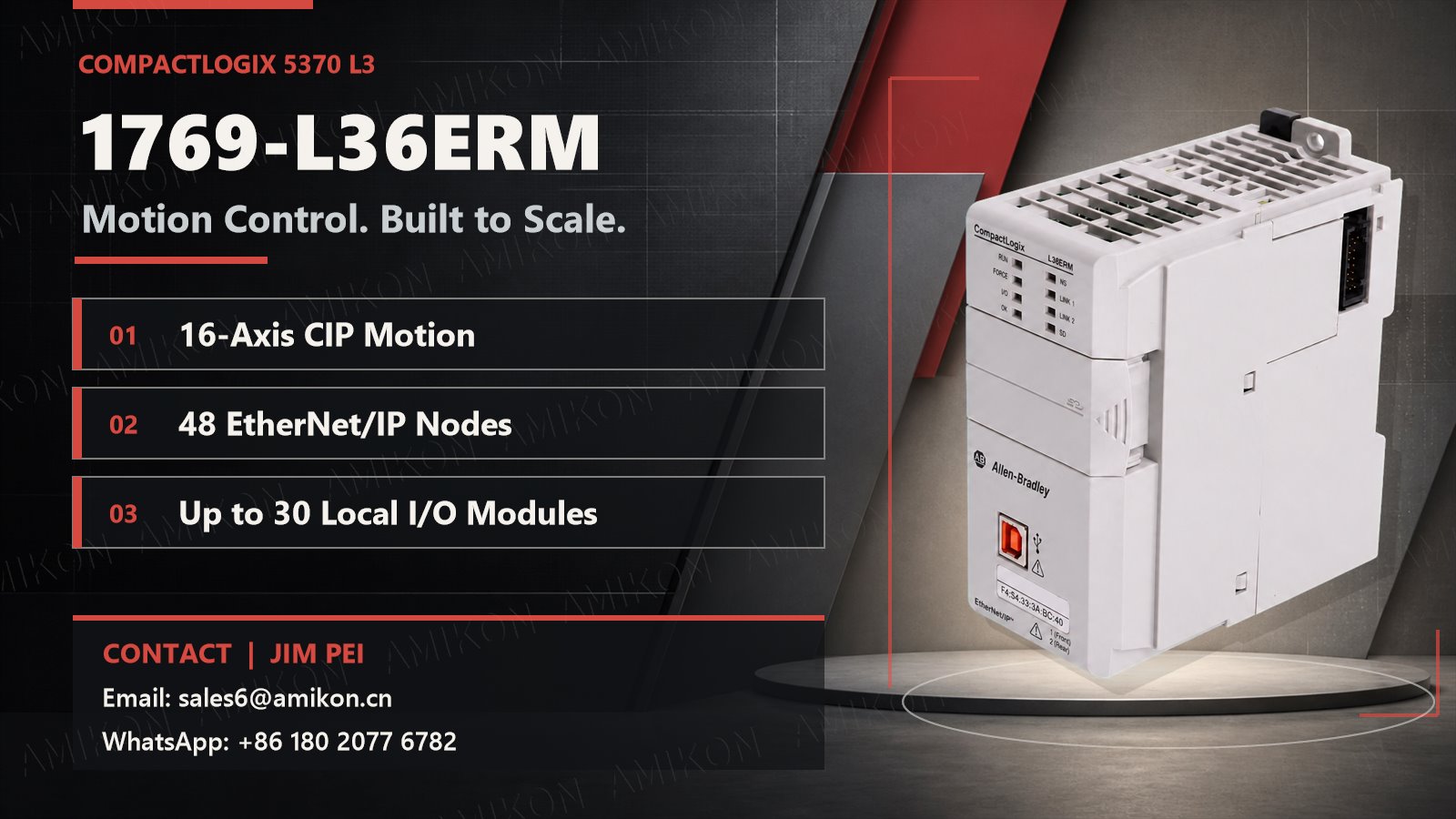
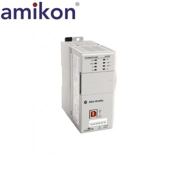
    When a machine evolves from a few simple movements to more than ten servo axes, dozens of I/O modules, and a large number of EtherNet/IP devices, controller selection is no longer just about comparing memory size. Engineers also need to consider motion capacity, network scale, future expansion, the continued usability of existing I/O, and the ease of future maintenance. The Allen-Bradley 1769-L36ERM is a CompactLogix 5370 L3 motion controller that provides 3 MB of user memory, dual EtherNet/IP ports, up to 16 CIP motion position loop axes, 48 EtherNet/IP nodes, and 30 local 1769 Compact I/O modules. It is more suitable for medium to large-sized machines that have exceeded the capacity of a small PLC but do not require a large control system. Which projects should consider the 1769-L36ERM? The 1769-L36ERM is generally worth considering if the project meets the following criteria: - The equipment needs to control 8 or more, up to 16 CIP motion position loop axes; - The 16 local I/O modules are insufficient for expansion needs; - The number of EtherNet/IP nodes is approaching or exceeding 32; - Logic, motion, and equipment communication need to be handled within a single platform; - The existing production line already uses 1769 Compact I/O; - Future additions of workstations, drives, detection, or barcode scanners are possible. If the equipment has only a small number of motion axes and I/O, the 1769-L33ERM may be sufficient; if the program, data, and network scale are larger, the 1769-L37ERM or a newer generation control platform should be evaluated. Key Technical Features and Practical Value Integrated Logic and Motion Control The 1769-L36ERM supports up to 16 CIP motion position loop axes and kinematic functions. Device logic, motion commands, axis states, and interlock conditions can all be managed within a single Studio 5000 project. For machine manufacturers, this helps reduce the need for separate motion controllers and their communication interfaces; for commissioning engineers, it makes it easier to troubleshoot from program conditions, axis states, and field I/O. Dual EtherNet/IP Ports and DLR Capability Two EtherNet/IP ports are part of the controller's internal switching structure and share a single IP address, usable in linear networks or DLR device-level ring networks. Linear structures simplify wiring between devices; with proper DLR configuration, they help reduce the risk of a single link failure causing a complete network communication outage. Note that related devices in the network must also support DLR. 30 Local 1769 I/O Modules The L36ERM supports up to 30 local 1769 Compact I/O modules, distributed across up to three module groups. For multi-station equipment, this means the control system can connect to more sensors, valve islands, analog inputs, and dedicated modules. For legacy equipment already using the 1769 I/O architecture, continuing to use the same I/O system may reduce rewiring and cabinet modifications, but module ...
    view more

  • Schneider TSXP57302M Unexpected Stop: How to Read the Last Stop Record Before Replacing the CPU
    Schneider TSXP57302M Unexpected Stop: How to Read the Last Stop Record Before Replacing the CPU 2026-08-29
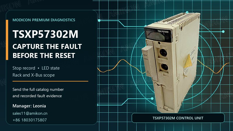
    Schneider TSXP57302M Unexpected Stop and Fault Diagnosis | Amikon An unexpected STOP on a Schneider TSXP57302M can create immediate pressure to order a replacement CPU. Yet the state of one LED, or the fact that the application is no longer running, does not by itself identify a failed processor. The useful evidence is the combination of the last-stop record, the front-panel indicators, the rack-level system bits and the event that occurred just before production stopped. This diagnostic sequence is designed for maintenance and purchasing teams working with a Premium installation. It helps separate a command-driven stop, a task watchdog, a power interruption, a hardware fault and a software fault before a spare is selected or the installed unit is removed. A STOP Event Is Not Proof of a Failed CPU The first question is not “Which CPU should we buy?” It is “Why did this CPU stop?” A transition from RUN to STOP can come from the programming terminal or a dedicated input. It can also follow a task watchdog, a loss of power, a locked memory card, a hardware fault or a software fault. Those causes lead to different field actions and different purchasing decisions. If the stop was commanded, exchanging the TSXP57302M will not correct the initiating condition. If the event followed a power loss, the investigation should include supply continuity and the state of the memory card. If the record points to an I/O or X-Bus condition, the processor may only be reporting a fault elsewhere in the station. A replacement becomes a sound decision only after those alternatives have been narrowed down. Read %SW58 Before Making a Hardware Decision The Premium processor retains a compact record of its last stop in system word %SW58. The most significant byte stores the day of the week, from 1 to 7. The least significant byte stores the stop code. For example, 16#0201 records Tuesday and stop code 1. Capture the full hexadecimal value; writing down only the final digit removes useful context. Stop code Recorded condition First field check 1 RUN-to-STOP command from the terminal or dedicated input Confirm who or what issued the stop request. 2 Task or SFC watchdog Review task execution and the event immediately before the overrun. 4 Power outage or memory-card lock Check the power event and memory-card state before disturbing the rack. 5 Hardware fault Correlate the record with ERR, I/O and rack diagnostics. 6 Software fault Preserve %SW125 and the application context. From Front-Panel LEDs to the Fault Domain Five front-panel indicators provide a fast route into the diagnosis. RUN describes the execution state. ERR points toward the processor, the system or an onboard PCMCIA device. I/O directs attention to module, channel or configuration faults. TER shows activity on the terminal port, while FIP applies only to processor references equipped for that network. Observed state Diagnostic meaning What to preserve RUN flashing STOP state or a blocking software error %SW58,...
    view more
  • GE FANUC A06B-6117-H209 Servo Drive: Everything You Need to Know for CNC Upgrades
    GE FANUC A06B-6117-H209 Servo Drive: Everything You Need to Know for CNC Upgrades 2026-08-18
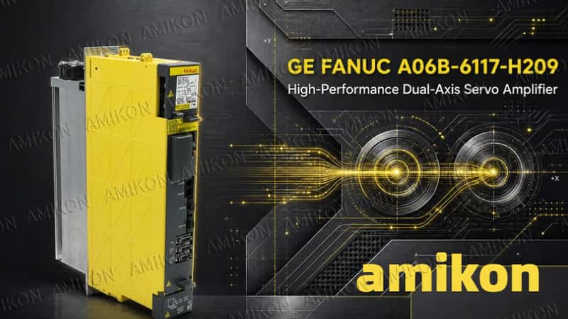
    Modern CNC machine tools depend on a servo system that can translate nanometre-scale commands into stable, repeatable axis motion. When a servo amplifier fails, the result is rarely a minor inconvenience: the machine may lose axis readiness, stop mid-cycle, or remain out of production while maintenance teams search for a compatible replacement. The GE FANUC A06B-6117-H209, also designated FANUC αiSV 80/80, is a two-axis servo amplifier module for the 200 V-class αi drive system. It combines two servo channels in one module and communicates with the CNC through FANUC Serial Servo Bus (FSSB). For plants maintaining established FANUC-controlled equipment, obtaining the correct H209 configuration can be the difference between a controlled repair window and extended downtime. Key Technical Features of the A06B-6117-H209 Specification snapshot FANUC order specification: A06B-6117-H209 Amplifier model: αiSV 80/80 Architecture: two-axis servo amplifier, L axis and M axis System class: 200 V input-series drive system CNC interface: FSSB optical interface Rated output current: 19 Arms per axis Nominal current limit: 80 Apeak per axis; the standard peak value can vary by approximately ±10% with circuit constants Servo control support: HRV2 and HRV3 Main-circuit control: sine-wave PWM control using an IGBT bridge These figures matter because “80/80” is a FANUC amplifier designation, not an invitation to match by motor kilowatts alone. The αiSV module must be selected for the connected servo motors. Motor model, current requirement, acceleration profile, duty cycle and paired power-supply capacity must all be considered. Dual-axis control in a compact module The H209 drives two axes from one amplifier. Separate CZ2L/CZ2M motor-power connections and ENC1/JF1 and ENC2/JF2 Pulsecoder inputs serve the L and M axes. This architecture reduces cabinet space and cabling compared with two independent amplifiers, while preserving axis-specific feedback and diagnostics. High-response digital servo performance The module supports FANUC SERVO HRV2 and HRV3 control. SERVO HRV is a digital current-control method designed for higher speed, precision and acceleration. It combines high-speed digital signal processing, high-precision amplifiers and detectors, and filters for suppressing low-frequency machine vibration. HRV2 uses a 125 μs current loop, while HRV3 uses a 62.5 μs current loop. The standard H209 is not the later “L” version intended for HRV4. FANUC also pairs its servo systems with high-resolution feedback devices. On the H209, the two dedicated Pulsecoder channels and the fast FSSB link form the hardware path for precise closed-loop control. Encoder type, motor specification and servo parameters must still match the machine configuration. Protection and thermal monitoring The amplifier provides status and alarm diagnostics rather than failing silently. Relevant fault indications include inverter overheat, radiator cooling-fan stop, DC-link current, IPM overheat, u...
    view more
  • Honeywell 10014/I/F Communication Module: A Practical Guide for Legacy FSC Connectivity
    Honeywell 10014/I/F Communication Module: A Practical Guide for Legacy FSC Connectivity 2026-08-15
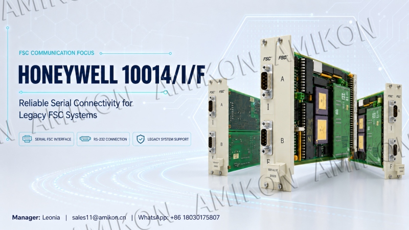
    01 FSC Context and the Role of the Communication Module Keeping a legacy safety system dependable is rarely about one dramatic upgrade. More often, it depends on understanding the quiet components that move information between controllers, supervisory systems and engineering tools. The Honeywell 10014/I/F communication module belongs to that category. It is associated with Honeywell’s Fail Safe Controller, or FSC, platform and appears in serial communication arrangements documented for FSC controllers. For plants that still operate an FSC installation, the module matters because communication is the route by which essential controller data becomes visible to the wider automation environment. Honeywell describes FSC as its first-generation safety controller and identifies it as a SIL 3-certified integrated safety platform. The system was built around Quadruple Modular Redundant technology and served high-integrity process control, burner and boiler management, emergency shutdown, turbine and compressor safeguarding, fire and gas detection, and pipeline monitoring duties. Within this architecture, the Honeywell 10014/I/F should be viewed in context: it supports communication around a safety controller whose primary job remains the execution of configured safety functions. Official Honeywell integration guidance identifies 10014 variants among the communication modules used for a serial FSC controller connection. The RS-232 link is made to the controller COM module, with the 10004 and 10014 families named as applicable types. This places the Honeywell 10014/I/F at a defined boundary between the FSC controller and a serially connected host or server. It is not a field input card and should not be described as a general-purpose digital I/O module. That distinction is important during maintenance. A communication module can affect the availability of operating information without changing the underlying separation between safety execution and supervisory access. Honeywell explains that FSC provides dual-redundant, fault-tolerant control for safety and shutdown applications on the TotalPlant Solution Universal Control Network. Safety functions can be integrated into the overall architecture while emergency shutdown functions remain isolated from process control strategies on a separate safety network. The Honeywell 10014/I/F therefore sits within a carefully structured system, not as a stand-alone networking accessory. 02 Serial Integration and Controller Addressing FSC was designed to exchange information with other parts of the Honeywell control environment. Honeywell states that integration permits peer-to-peer communication with Process Managers, Advanced Process Managers, High-Performance Process Managers and Logic Managers. Higher-level strategies communicate through Application Modules and host computers on the Local Control Network. In a serial connection scenario, the Honeywell 10014/I/F helps form the communication path used to expose selected...
    view more
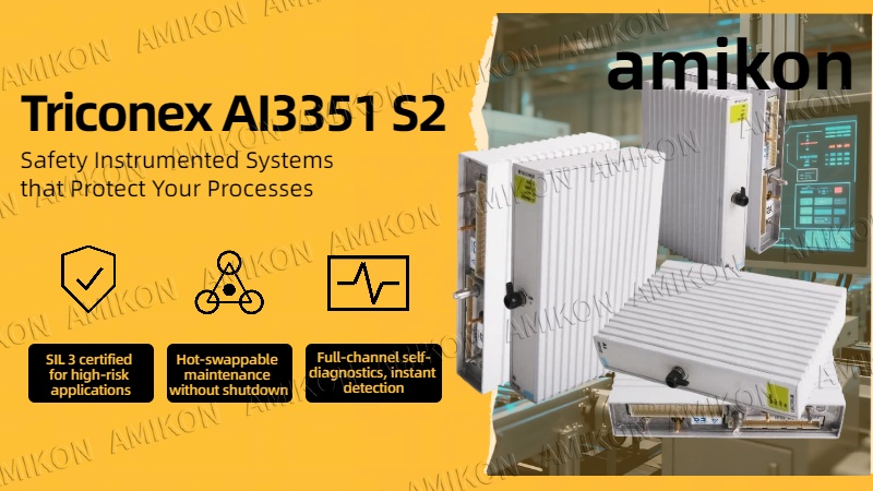
  • Triconex AI3351 S2 Analog Input Module: Building a Safety Defense Line for Industrial Automation Control Systems
    Triconex AI3351 S2 Analog Input Module: Building a Safety Defense Line for Industrial Automation Control Systems 2026-08-04
    1. Introduction In modern high-risk process industries, such as oil and gas extraction, refining and chemical processing, nuclear power, and large-scale emergency shutdown (ESD) systems, ensuring the safe and continuous operation of equipment is crucial. Even minor control errors or instrument malfunctions can trigger catastrophic safety accidents. Triconex, a global leader in functional safety, offers the Triconex AI3351 S2 Analog Input Module, a core hardware component designed specifically for safety instrumented systems (SIS) with stringent requirements for high reliability and availability. As a key component in a triple modular redundancy (TMR) architecture, the AI3351 S2 can acquire 4-20 mA analog signals from field transmitters with extremely high accuracy and filters transient noise and single-point hardware failures through a sophisticated internal voting mechanism, ensuring the system remains rock-solid even in complex industrial environments. This article will provide an in-depth analysis of the module's technical parameters, application scenarios, core advantages, and key points for installation and maintenance, offering professional reference for factory engineers and overseas buyers. 2. Technical Specifications The Triconex AI3351 S2 module adheres to extremely high industrial-grade standards in its hardware design. The following are the core technical parameters and performance indicators of this module: Product Model: Triconex AI3351 S2 (Model 3351 Analog Input Module) Number of Input Channels: 32 Points, Commoned Nominal Input Current: 4 - 20 mA DC Operational Current Range: 2 - 22 mA DC (Supports 6% Full-Scale Overload) Input Bandwidth: 16 Hz (-3dB) Input Impedance: Internal sampling resistor 100Ω ± 0.01%, total input impedance with socket approximately 250Ω Resolution: 12-bit analog-to-digital conversion Absolute Error: Better than 0.15% of full scale (20 mA) Matching Socket and Terminals: Model Model 2351 (direct wiring dock) or Model 2352 (external terminal block dock, supports 9764-310 RTD/TC/AI signal conditioning board) Online self-diagnosis: Built-in Force-to-Value Diagnostic (FVD), full channel scan time less than 1 ms 3. Application Fields Thanks to its unparalleled fault tolerance and SIL 3 functional safety certification, the Triconex AI3351 S2 is widely used in critical process industries with extremely high requirements for safety and continuous operation: Oil & Gas: Pressure, temperature, and flow monitoring and emergency shutdown of offshore drilling platforms and oil and gas pipelines. Refining & Petrochemical: Critical parameter acquisition in high-temperature, high-pressure, flammable, and explosive areas such as cracking furnaces, hydrogenation units, and catalytic reforming. Nuclear & Power Generation: Reactor protection systems, turbine overspeed protection, and boiler combustion safety monitoring systems (BMS). Emergency Shutdown (ESD) and Fire & Gas (F&G) Systems: As a core analog inpu...
    view more
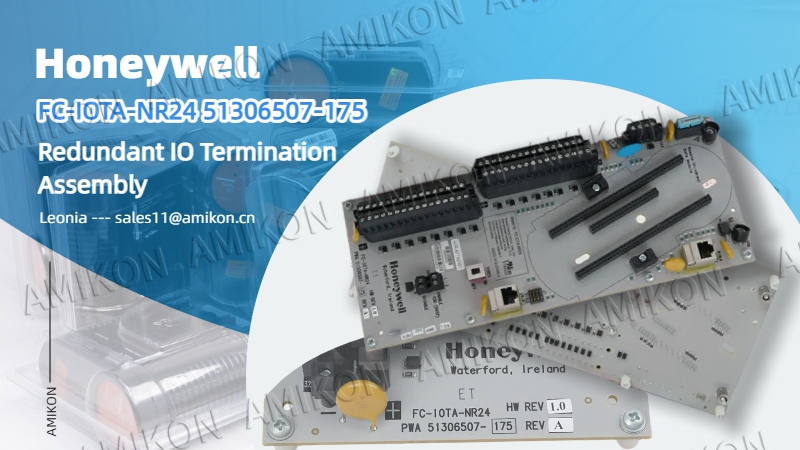
  • Honeywell FC-IOTA-NR24: SIL3 Level Non-Redundant I/O Terminal Assembly for Ensuring Safety Instrumented Signal Links in Process Industries
    Honeywell FC-IOTA-NR24: SIL3 Level Non-Redundant I/O Terminal Assembly for Ensuring Safety Instrumented Signal Links in Process Industries 2026-07-27
    I. FC-IOTA-NR24 Terminal Assembly Positioning The FC-IOTA-NR24 (also known as IOTA-NR24, part number 51306507-175) is a Honeywell field terminal assembly module, a non-redundant I/O terminal assembly unit designed specifically for use with RUSIO-3224 and RUSLS-3224 I/O modules. It is the core hardware within a safety management controller system that enables the interface between field signals and control modules. This terminal assembly complies with IEC 61508 and IEC 61511 functional safety standards and can be applied up to SIL3 level operating conditions. It is widely used in process industries such as petrochemical, oil and gas, power, and chemical industries with safety interlocking requirements. The entire component integrates signal terminals, Ethernet communication interfaces, power supply circuits, and hardware function DIP switches, providing a one-stop solution for field cabling and connection of 32 general-purpose I/O channels, significantly simplifying cabling planning within the Safety Instrumented System (SIS) cabinet. II. Core Functional Architecture and Hardware Design The FC-IOTA-NR24 is equipped with three Weidmüller terminal blocks, clearly defining signal circuits: CN1 carries I/O signals from channels 1 to 16, CN2 carries I/O signals from channels 17 to 32, and CN3 provides four independent V+ power supply interfaces specifically for powering active analog input instruments. The negative terminals of CN1 and CN2 terminal blocks are connected to 0V, while the positive terminals correspond to independent signal channels, compatible with various general-purpose field I/O signal inputs. For communication, it features two shielded RJ45 Ethernet interfaces, RIOLA and RIOLB, constructing a 100Mbps dual-link Ethernet communication channel, serving as Link A and Link B respectively, enabling data interaction between the I/O module and the safety controller. The hardware integrates a power toggle switch, enabling local control of module power-on and power-off. Reserved jumper positions for node addresses allow for setting device node addresses via dedicated jumper components. Hardware enable switching for ESD emergency shutdown is supported, with 32 channels offering flexible selection between general IO mode and ESD emergency stop input mode. The component requires mounting on the MCAR-01 series metal mounting base, which integrates a grounding rail, a 24V DC power supply rail, and a 0V rail, providing a stable power supply and reliable grounding loop for the entire terminal assembly. III. FC-IOTA-NR24 Complete Technical Specifications General Parameters Model: FC-IOTA-NR24 (IOTA-NR24) Operating Temperature: -40℃ ~ +70℃ Storage Temperature: -40℃ ~ +85℃ Relative Humidity: 10~95% (non-condensing) Pollution Degree: Level 2 and above Certifications: CE, UL, TUV Power Supply: 24V DC, voltage fluctuation range -15%~+30%, maximum load 10A Polarization Protection: Parallel diode reverse connection protection (fault-triggered fuse blows) CN3 ...
    view more
first page 1 2 3 4 5 6 7 8 9 10 last page

A total of 44 pages

welcome to Amikon Limited
If you have questions or suggestions,please leave us a message,we will reply you as soon as we can!

Home

Products

about

contact