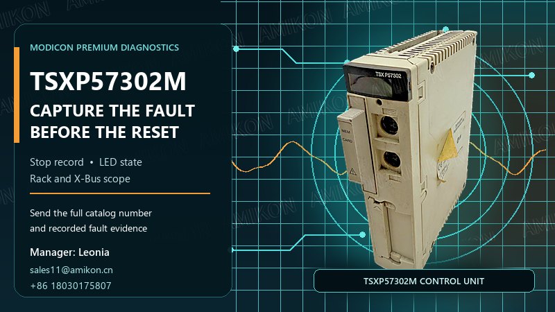
An unexpected STOP on a Schneider TSXP57302M can create immediate pressure to order a replacement CPU. Yet the state of one LED, or the fact that the application is no longer running, does not by itself identify a failed processor. The useful evidence is the combination of the last-stop record, the front-panel indicators, the rack-level system bits and the event that occurred just before production stopped.
This diagnostic sequence is designed for maintenance and purchasing teams working with a Premium installation. It helps separate a command-driven stop, a task watchdog, a power interruption, a hardware fault and a software fault before a spare is selected or the installed unit is removed.
The first question is not “Which CPU should we buy?” It is “Why did this CPU stop?” A transition from RUN to STOP can come from the programming terminal or a dedicated input. It can also follow a task watchdog, a loss of power, a locked memory card, a hardware fault or a software fault. Those causes lead to different field actions and different purchasing decisions.
If the stop was commanded, exchanging the TSXP57302M will not correct the initiating condition. If the event a power loss, the investigation should include supply continuity and the state of the memory card. If the record points to an I/O or X-Bus condition, the processor may only be reporting a fault elsewhere in the station. A replacement becomes a sound decision only after those alternatives have been narrowed down.
The Premium processor retains a compact record of its last stop in system word %SW58. The most significant byte stores the day of the week, from 1 to 7. The least significant byte stores the stop code. For example, 16#0201 records Tuesday and stop code 1. Capture the full hexadecimal value; writing down only the final digit removes useful context.
| Stop code | Recorded condition | First field check |
|---|---|---|
| 1 | RUN-to-STOP command from the terminal or dedicated input | Confirm who or what issued the stop request. |
| 2 | Task or SFC watchdog | Review task execution and the event immediately before the overrun. |
| 4 | Power outage or memory-card lock | Check the power event and memory-card state before disturbing the rack. |
| 5 | Hardware fault | Correlate the record with ERR, I/O and rack diagnostics. |
| 6 | Software fault | Preserve %SW125 and the application context. |

Five front-panel indicators provide a fast route into the diagnosis. RUN describes the execution state. ERR points toward the processor, the system or an onboard PCMCIA device. I/O directs attention to module, channel or configuration faults. TER shows activity on the terminal port, while FIP applies only to processor references equipped for that network.
| Observed state | Diagnostic meaning | What to preserve |
|---|---|---|
| RUN flashing | STOP state or a blocking software error | %SW58, %SW125 and the application state |
| ERR on or flashing | Processor/system, application, PCMCIA or X-Bus-related condition | Exact LED pattern and memory-card state |
| I/O on | Module, channel or configuration fault | Faulted rack, slot, module and channel |
| ERR and I/O flashing together | X-Bus error | Rack topology, extension cabling and termination details |
Record whether each LED is on, off or flashing. “Red light present” is not a complete service note. A photograph that captures all indicators, the rack and the installed memory card is more useful than a close-up of one lamp.
%S10 indicates an I/O error on X-Bus or Fipio. %S16 indicates an I/O error in the current task. Read them together with the I/O LED and the configuration view. If the CPU reports an I/O condition while the processor functions remain available, trace the fault to the rack, module and channel before replacing the controller.
System bits %S40 through %S47 map I/O errors to racks 0 through 7. This makes the field note specific: instead of “Premium PLC stopped,” it can state which rack raised the error. That distinction can change the required spare from a CPU to a rack, power, I/O or interconnection component.
When stop code 6 identifies a software fault, retain %SW125. It provides the detailed nature of the blocking condition. Nonblocking program errors can involve string handling, capacity or arithmetic limits, and index overflow; depending on configuration, some can be converted into blocking errors. After a serious processor or system fault forces the PLC into ERROR, communication with the diagnostic device may no longer be available. Following the required cold restart, information can be recovered through %SW124; values H'80 and H'81 are associated with X-Bus cabling diagnosis.
Do not remove a programmed processor as the first diagnostic step. When a TSX P57 processor is replaced with a unit that is not blank, power to all control units in the PLC station must be switched off. Plan the shutdown, preserve the application and memory-card arrangement, and label every connection before hardware is moved.
A CPU replacement is better supported when the last-stop record identifies a hardware fault, the ERR pattern and system information point back to the processor or its onboard device, external rack and power conditions have been checked, and the fault cannot be isolated to an I/O channel or X-Bus segment. Purchasing should receive the complete catalog number together with the diagnostic record—not just a photo of the cabinet.
For a service spare, the objective is to restore the existing engineered configuration. A similar Premium processor name is not enough: memory arrangement, ports, installed application and rack context must be matched to the station record before installation.
Send a clear image of the complete catalog number, rack position, memory-card arrangement and connected ports. Include the %SW58 value, the LED pattern and any affected rack or slot. This allows the request to be checked against the installed configuration rather than against the model name alone.
No. A flashing RUN indicator can represent the STOP state or a blocking software error. Read %SW58 and, when applicable, %SW125 before deciding that the processor hardware is the cause.
Treat the combined flashing pattern as an X-Bus lead. Record %S10 and %S40–%S47, then inspect the indicated rack, extension path, connectors and termination. Keep the original LED pattern and system-word values in the maintenance record.
Preserve the complete %SW58 value, %SW125, the application state and the event sequence that preceded the stop. A reset can remove the most useful context for distinguishing an application condition from a hardware problem.
Switch off power to all control units in the PLC station before installing a processor that is not blank. Label the ports and memory-card arrangement and protect the retained application before the exchange begins.
| Allen-Bradley 150-F43NBDD | Siemens 6ES7193-6AR00-0AA0 | ABB AC522 |
| Emerson 1C31113G05 | Honeywell TC-OAV081 | GE IS200ECTBG1A |
| Allen-Bradley 150-F251NZD | Siemens 6ES7214-1AF40-0XB0 | ABB AI523 |
| Emerson 1C31122G01 | Honeywell MC-PSTX03 | GE IS200ACLEH1BCB |
| Allen-Bradley 150-F43NBD | Siemens 6ES7214-1AG40-0XB0 | ABB AI531 |
| Emerson 1C31129G04 | Honeywell TK-FPDXX2 | GE IS200EDCFG1AED |
| Allen-Bradley 150-F60NBD | Siemens 6ES7214-1BG40-0XB0 | ABB AI561 |
| Emerson 1C31166G02 | Honeywell 8C-TAIXA1 | GE IS200DSPXH1DBD |
| Allen-Bradley 150-F85NBD | Siemens 6ES7215-1AF40-0XB0 | ABB AI562 |
| Emerson 1C31189G03 | Honeywell 8C-TCNTA1 | GE IS200EPDMG1A |
| Allen-Bradley 150-F135NBD | Siemens 6ES7215-1AG40-0XB0 | ABB AI563 |
| Emerson 1C31194G01 | Honeywell FC-IO-0001 | GE IS220UCSAH1A |
| Allen-Bradley 150-F108NBD | Siemens 6SL3120-2TE15-0AA4 | ABB AO522 |
| Emerson 1C31194G03 | Honeywell CC-TDI230 | GE IC752SPL013 |
| Allen-Bradley 150-F201NBD | Siemens 6SL3120-2TE21-0AA3 | ABB AO523 |
| Emerson 1C31197G01 | Honeywell CC-TDI220 | GE DS200DMCBG1A |
| Allen-Bradley 150-F361NBDD | Siemens 6SL3130-7TE21-6AA1 | ABB AO561 |
| Emerson 1C31199G05 | Honeywell DC-TAIX51 | GE IS200EDEXG1ADA |
| Allen-Bradley 150-F60NBRB | Siemens 6SL3210-1KE11-8UP2 | ABB AO562 |
| Emerson 1C31203G01 | Honeywell DC-TDIL11 | GE IS200ESELH2AAA |
Supplyed
525011

parts to
23253

customers in
148

countries



Disclaimer:
Amikon sells new and surplus products and develops channels for purchasing such products. This website has not been approved or recognized by any of the listed manufacturers or trademarks.
Amikon is not an authorized distributor, dealer, or representative of the products displayed on this website. All product names, trademarks, brands, and logos used on this website are the property of their respective owners. The description, explanation, or sale of products with these names, trademarks, brands, and logos is for identification purposes only and is not intended to indicate any association with or authorization from any rights holder.
Powered by amikonplc.com