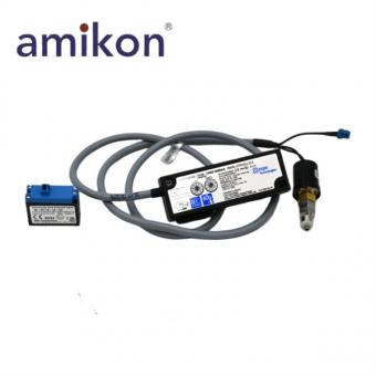
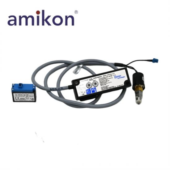
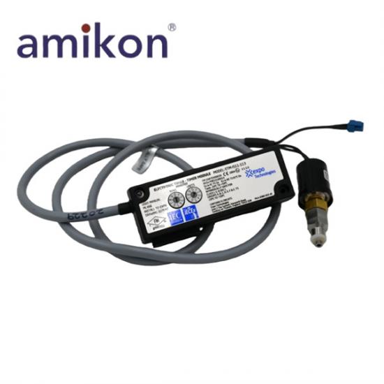
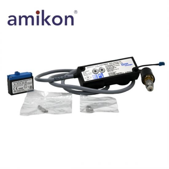
Intrinsically safe electronic timer module references for MiniPurge timing assemblies.
Services: Stock check · Fast response · Global delivery
Leonia: sales11@amikon.cn · +86 18030175807
Brand:
Other Hot-sellingsItem NO.:
ETM-IS11-113Payment:
T/TLead Time:
Confirm by RFQManufacturer:
Expo Technologies LtdPart number:
ETM-IS11-113 / ETM-IS51-113Electronic purge-timing module references with intrinsically safe protection and staged cycle indication.
Expo Technologies ETM-IS11-113 and ETM-IS51-113 are references within the ETM intrinsically safe electronic timer-module family used in MiniPurge purge and pressurization control arrangements. The timer participates in the purge sequence after the required purge-flow condition has been detected.
The timing period is selected at the module. During the active cycle, four LEDs provide a staged indication of elapsed purge time. The exact installed code, timer label and host control-unit arrangement should be matched when sourcing a replacement module.
| Manufacturer | Expo Technologies Ltd |
|---|---|
| Models | ETM-IS11-113 / ETM-IS51-113 |
| Product type | Electronic timer modules |
| Product code family | ETM-IS**-*** |
| System context | MiniPurge purge and pressurization systems |
| Timing method | Electronic timer (ET) |
| Timer setting interface | Selector switches on the timer module |
| Purge-time range | 1 to 99 minutes in 1-minute intervals |
| 00 setting | Continuous purging; the timing cycle does not complete |
| Progress indication | Four LEDs indicate 0–25%, 26–50%, 51–75% and 76–100% of the purge period |
| Protection concept | Intrinsic safety “i” |
| Applicable directive | ATEX Directive 2014/34/EU |
| Applied standards | EN IEC 60079-0:2018; EN 60079-11:2012 |
| Notified body | ExVeritas, No. 2804 |
| Maintenance interval | Electronic-timer maintenance every 3 years, including battery-pack replacement and repeat commissioning tests |
The purge-flow sensor signal starts the electronic timing period. Selector switches on the timer module set the required interval, with one-minute steps through the documented timing range. Setting the timer to 00 holds the system in continuous purging and prevents the normal timing cycle from completing.
Four LEDs indicate progression through the purge period in quarter-cycle stages. This gives the operator a visible timing reference while verifying that the measured purge duration is not shorter than the required value.
ETM-IS11-113 and ETM-IS51-113 should be identified from the complete nameplate code, not from the ETM prefix alone. Record the control-unit model, timer-switch arrangement and battery-pack configuration before removal.
Electronic-timer maintenance is scheduled at three-year intervals. The associated intrinsically safe battery pack is replaced and the commissioning tests are repeated. A discharged battery or a 00 timer setting are specific checks when a purge timing sequence does not complete as expected.
Provide the complete timer code, a clear photo of the timer label, the MiniPurge control-unit identification and the installed timer-switch and battery arrangement. The full suffix must be matched because ETM variants are covered as a family but are not identified as automatically interchangeable.
Do not assume direct interchangeability from the shared ETM prefix. Match the complete code and the installed purge-system configuration before replacement; the connected timer switch, battery arrangement and control-unit version are part of the site check.
A timer setting of 00 produces continuous purging, so the cycle does not complete. If this is not the intended condition, verify the selector setting and then repeat the required commissioning checks.
Four LEDs flash sequentially to show the elapsed portion of the purge period: 0–25%, 26–50%, 51–75% and 76–100%. The recorded purge time must be equal to or greater than the required purge time.
Plan electronic-timer maintenance at three-year intervals. Replace the associated intrinsically safe battery pack and repeat the commissioning tests; the system identity and timer settings should be recorded before maintenance begins.
| Recommended Model | Recommended Model | Recommended Model |
|---|---|---|
| RADISYS PSBC486DX66 | AKT seriplex 0190-713 | KONTRON SOKO EURO-386SL |
| MURPHY C3-1A E6-K-0115 | ALSTOM VP 325 02X | varian VME1-2 04-719030-01 |
| Allen-Bradley 150-F251NBD | Schneider GS1NG3 | Saia Burgess Controls PCD3W800 |
| HBM WA/20mm 050310129 090610052 | Hitachi 33016136-5 | Bosch Rexroth 0811405029 |
| G.M. International D1064S | ABB RT7-34T | Balluff BAE PS-XA-3Y-24-400-008;BAE000A |
| Siemens 3NJ4133-3BF11 | Lenze CDD34.017 | INDUSTRONIC 341-720-300 12 DAL 03 |
| Festo MPPES31410420 | Yaskawa SGM04U314 | Mitsubishi FX-24MT-ESS |
| Beckhoff KL3052 | Siemens 3TK2824-1AL20 | Lenze CDD34.005.C2.1 |
| Allen-Bradley 150-F251NBDD | Bosch Rexroth 0811405007 1 818 310 002-4V0 | Omron H8PS-8B |
| SEW-EURODRIVE MDX61B0011-5A3-4-0T | Allen-Bradley 150-F251NBR | Bosch Rexroth VT-VRPA 1-537-10-V0-QV 0811405099 |
| Omron NB7W-TW01B-V1 | SEW-EURODRIVE MC07B0030-5A3-4-00 | Allen-Bradley 150-F251NBRB |
| Bosch Rexroth 0 811 405 007 0811405007 1 818 310 002-4V0 | Omron CJ1W-AD081-V1 | SEW-EURODRIVE MDX61B0015-5A3-4-0T/DEH11B/DFE32B |
| Allen-Bradley 150-F251NBRD | Omron CP1L-EM30DR-D | SEW-EURODRIVE MC07B0005-5A3-4-00/FSC11B/DFP2 |
| Allen-Bradley 150-F85NBRB | Omron CP1L-M60DR-D | SEW-EURODRIVE MC07B0055-5A3-4-00 + MDX60A0054-5A3-4-00 |
| Mitsubishi FX3U-4DA | Siemens 6FX11422BA02 | Allen-Bradley 150-F135NBRD |
| Omron CJ1W-PTS52 | SEW-EURODRIVE MC07B0022-5A3-4-00 | Mitsubishi FX-48ER |
| Siemens 3RX9400-0AA00 | Allen-Bradley 150-F135NCD | Omron CP1L-M60DT1-D |
| SEW-EURODRIVE MDX60A0055-5A3-4-00 | Mitsubishi FX-8EX-A1 | Siemens 6FC5247-0AF11-0AA0 |
| Allen-Bradley 150-F135NCDB | Omron CJ1W-CT021 | SEW-EURODRIVE MDX60A0110503400 8226857 |
| Mitsubishi FX3U-4DA-ADP | Siemens 6FX1142-2BA02 | Allen-Bradley 150-F135NCDD |
Manager: Leonia
Email: sales11@amikon.cn
WhatsApp: +86 18030175807
Supplyed
525011

parts to
23253

customers in
148

countries
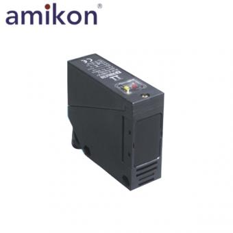 Pepperl+Fuchs RLK39-8-2000 ▏Sensor Photoelectric Switch
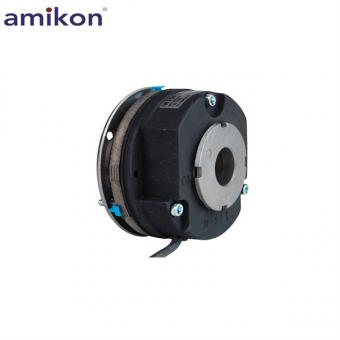 INTORQ BFK458-12E service brake
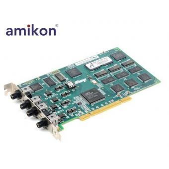 SST DNP-PCI-4 SST-DNP-PCI-4 Interface Card in New Condition
 YASKAWA CP-317/261IFM JACP-317261 Control Unit
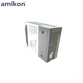 Molex DRL-DPM-BKF Adapter Card
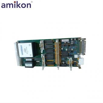 KONGSBERG NA-1E222.1 Power Card
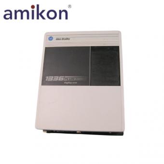 1336F-BRF150-AA-EN ▏1336 PLUS II Drive - 15 HP
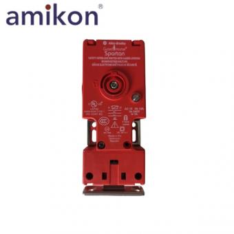 440G-S36001 ▏Guardmaster Solenoid Guard Locking Switch 24VAC/DC
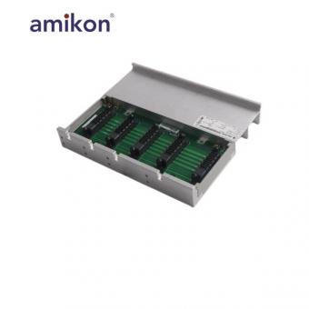 2093-PRS4 Kinetix 2000 4 Axis Slim Power Rail
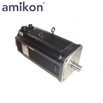 1326AB-B720E-M2K7L/B ▏AC Servo Motor
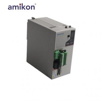 2093-AM02 Power module



Disclaimer:
Amikon sells new and surplus products and develops channels for purchasing such products. This website has not been approved or recognized by any of the listed manufacturers or trademarks.
Amikon is not an authorized distributor, dealer, or representative of the products displayed on this website. All product names, trademarks, brands, and logos used on this website are the property of their respective owners. The description, explanation, or sale of products with these names, trademarks, brands, and logos is for identification purposes only and is not intended to indicate any association with or authorization from any rights holder.
Powered by amikonplc.com